
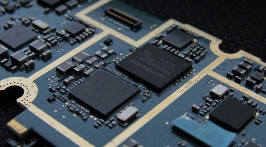
To evaluate high-reliability PCB assembly services, look for an inspection and test plan tied to your product requirements, clearly defined acceptance criteria, documented coverage limitations, and revision-controlled records linked to each assembly or production lot. Equipment lists and certification certificates alone do not show what a supplier will verify on your board.
The PCB assembly process needs complementary controls: visual inspection and automated optical inspection (AOI) assess accessible workmanship, X-ray examines selected hidden features, in-circuit testing checks accessible electrical characteristics, and functional testing evaluates specified operating behavior. Passing one method does not establish complete coverage by the others.
Where do inspection and testing fit in the PCB assembly process?
PCB assembly turns a fabricated bare circuit board into a populated electronic assembly. A typical surface-mount workflow includes document and material verification, solder paste printing, component placement, reflow soldering, inspection, electrical testing, and final release. Through-hole or mixed-technology builds add insertion and suitable soldering operations. Cleaning, programming, coating, and additional verification depend on the product requirements.
Quality checks belong throughout that sequence, not only at the shipping gate. Solder paste inspection can identify printing problems before placement. Post-reflow inspection can detect assembly anomalies before electrical testing. Reworked units need defined reinspection and retesting before release.
For the broader manufacturing sequence, see our comprehensive PCB assembly process guide. The focus here is how buyers can evaluate the evidence behind inspection, testing, and acceptance.
Which acceptance criteria should be agreed before production?
Start with a controlled requirements package. The purchase order, assembly drawing, quality agreement, and inspection plan should identify applicable standards, revisions, product class where relevant, customer-specific requirements, and the agreed order of precedence if documents conflict.
IPC-A-610 addresses electronic assembly acceptability, while J-STD-001 addresses requirements for soldered electrical and electronic assemblies, including materials, methods, and verification. The Global Electronics Association’s IPC certification overview explains these complementary scopes. Neither reference replaces a product-specific electrical test specification.
Ask the supplier to establish:
- Which characteristics are inspected, by which method, and at which production stage.
- Whether verification applies to every unit or a defined sample, with its rationale and escalation rules.
- Package-specific workmanship and hidden-joint acceptance criteria.
- Electrical limits, operating conditions, and required test results.
- Who can approve deviations, repairs, or use-as-is dispositions.
Do not accept a generic void-percentage limit for every hidden solder joint. Applicable criteria depend on the package, invoked requirements, and engineering assessment.
How do visual inspection, AOI, X-ray, and electrical tests compare?
What can visual inspection and AOI verify?
Manual visual inspection and AOI can identify accessible defects such as missing or displaced components, visible solder bridges, and certain polarity or workmanship anomalies. Detection depends on visibility, markings, lighting, magnification, camera geometry, and the inspection program.
Their main limitation is access: an optical system cannot directly evaluate solder connections concealed beneath a package. A visually correct component may also have the wrong electrical value or an internal fault. Ask how programs are approved, false calls are reviewed, and uninspectable features are handled. An AOI pass is not proof of electrical function.
What does X-ray inspection add?
X-ray can reveal selected hidden solder features beneath ball grid arrays and other bottom-terminated packages, including some bridges, voids, and missing solder connections. Its usefulness depends on resolution, viewing angle, package geometry, and whether the technique uses two-dimensional imaging or three-dimensional reconstruction.
Not every interface defect is readily detectable, and overlapping features can complicate interpretation. X-ray does not demonstrate firmware behavior or circuit operation. Request a package-specific inspection scope, approved criteria, image-retention requirements, and a documented process for resolving ambiguous findings.
What does in-circuit testing measure?
In-circuit testing (ICT) uses electrical access to evaluate selected components and circuit nodes. Depending on the design and test program, it can detect shorts, opens, incorrect component values, and other assembly faults. A bed-of-nails fixture supports repeatable access; flying-probe testing offers another approach with different throughput and access tradeoffs.
Coverage depends on test points, circuit topology, guarding, and measurement limits. Inaccessible nodes or parallel paths can leave gaps. Ask for the actual coverage report and exclusions, not simply confirmation that the supplier owns an ICT system. ICT does not establish complete system-level operation.
What does functional testing demonstrate?
Functional testing powers the assembly and evaluates defined behavior using specified firmware, inputs, loads, and interfaces. It may check power rails, communications, analog measurements, or operating sequences when included in the approved specification.
Its boundary is the test itself. A board that passes at room temperature under one load has not necessarily demonstrated performance across every temperature, timing condition, or fault scenario. Ask which requirements are exercised, which are excluded, and how failures are diagnosed. Functional testing complements structural inspection rather than making it unnecessary.
How should buyers evaluate test specifications and fixtures?
A useful test specification identifies the requirement being verified, setup, stimulus, expected response, numerical limits, measurement units, timing, and pass/fail logic. It should also define firmware versions, configuration settings, and any environmental conditions needed for repeatability.
For example, “verify the output voltage” is incomplete. The procedure needs an approved input condition, output load, settling time, measurement location, and allowable range. Engineering should establish those values from the product requirements, not copy generic limits from another assembly.
Fixtures require their own controls. Review fixture identification, drawing and wiring revisions, connector life, maintenance, and verification after repair. Confirm that measuring instruments have suitable accuracy and current calibration status. Reference assemblies can help detect setup changes, but should not be the only evidence that a test system works correctly.
Agree on fixture ownership, development responsibility, acceptance, and change costs before production. A board revision can require a new fixture interface, revised software, or additional validation.
How can a supplier demonstrate coverage without overstating it?
Request a coverage matrix linking critical requirements and likely failure modes to the inspection or test that addresses them. Record the accessible features, detection limits, exclusions, and approved treatment of residual risk.
For a hidden-joint device, X-ray might assess specified solder features while electrical testing checks accessible connections and selected behavior. Neither method alone necessarily detects every possible connection defect.
Distinguish unit coverage from defect coverage. “Every board is tested” describes test frequency, not proof that every fault can be detected. Any percentage claim should identify its denominator: components, nets, pins, requirements, or modeled faults. Document uncovered risks and the engineering decision behind any additional verification.
Which records support traceability and audit readiness?
Choose a completed, appropriately anonymized job and ask the supplier to reconstruct its production and acceptance history. The records should match the traceability depth and retention period agreed for your program.
- Build identity: assembly number and revision, serial or lot identifier, job traveler, and applicable material records.
- Verification configuration: inspection program, test software, firmware, procedure, and fixture revisions used.
- Results: inspection findings, required measurements, pass/fail decisions, timestamps, and operator or station identification.
- Equipment status: relevant calibration and maintenance evidence.
- Exceptions: nonconformance reports, authorized dispositions, rework history, and reinspection or retest results.
Retests should not erase the original failure. Preserving the sequence helps reviewers distinguish a corrected defect from an intermittent condition or test-contact problem. Document control should also prevent superseded programs and procedures from being used unintentionally.
A focused audit connects those records with personnel competency and corrective-action evidence. For wider sourcing considerations, see our guide to evaluating high-reliability PCB assembly services.
Frequently asked questions
Does passing AOI mean a PCB assembly works?
No. AOI evaluates programmed optical characteristics of accessible features. It does not establish electrical function, hidden-joint integrity, or complete component authenticity.
Does every high-reliability assembly need all four methods?
Not necessarily. The combination should follow design risks, package types, electrical access, contractual requirements, and required evidence. Confirm each method’s scope and availability for the specific program.
Does functional testing prove long-term reliability?
No. It demonstrates specified behavior under the tested conditions. Lifetime performance and environmental durability require separate engineering evaluation and, where applicable, qualification testing.
What should I request before accepting a supplier’s test plan?
Request approved acceptance criteria, the test specification, a coverage matrix, fixture controls, and a sample traceable results package. Review exclusions and release authority with engineering and quality before committing the build.
What is the next step for your program?
Bring your controlled drawings, assembly requirements, and test expectations to the supplier discussion. When discussing a build with American Precision Electronics, confirm the inspection methods, testing responsibilities, coverage limits, and documentation deliverables for your assembly. The goal is a defined PCB assembly process with evidence behind each release decision, not an assumption that one passing result proves everything.